


News
We'll get back to you as soon as possible.
How a Biogas Purification Plant Converts Raw Biogas into Pipeline-Grade Renewable Natural Gas
Raw biogas generated from anaerobic digestion typically contains 50–65% methane, 30–45% carbon dioxide, and a spectrum of trace contaminants including hydrogen sulfide, ammonia, siloxanes, and moisture. Without conditioning, this gas stream cannot be injected into natural gas networks or used as a vehicle fuel. A biogas purification plant addresses these challenges through a series of engineered separation and polishing steps, delivering biomethane that meets strict pipeline and end-use specifications. This article examines the core technologies, performance benchmarks, application environments, and system integration considerations that define modern purification facilities.
Core Purification Technologies in a Biogas Purification Plant
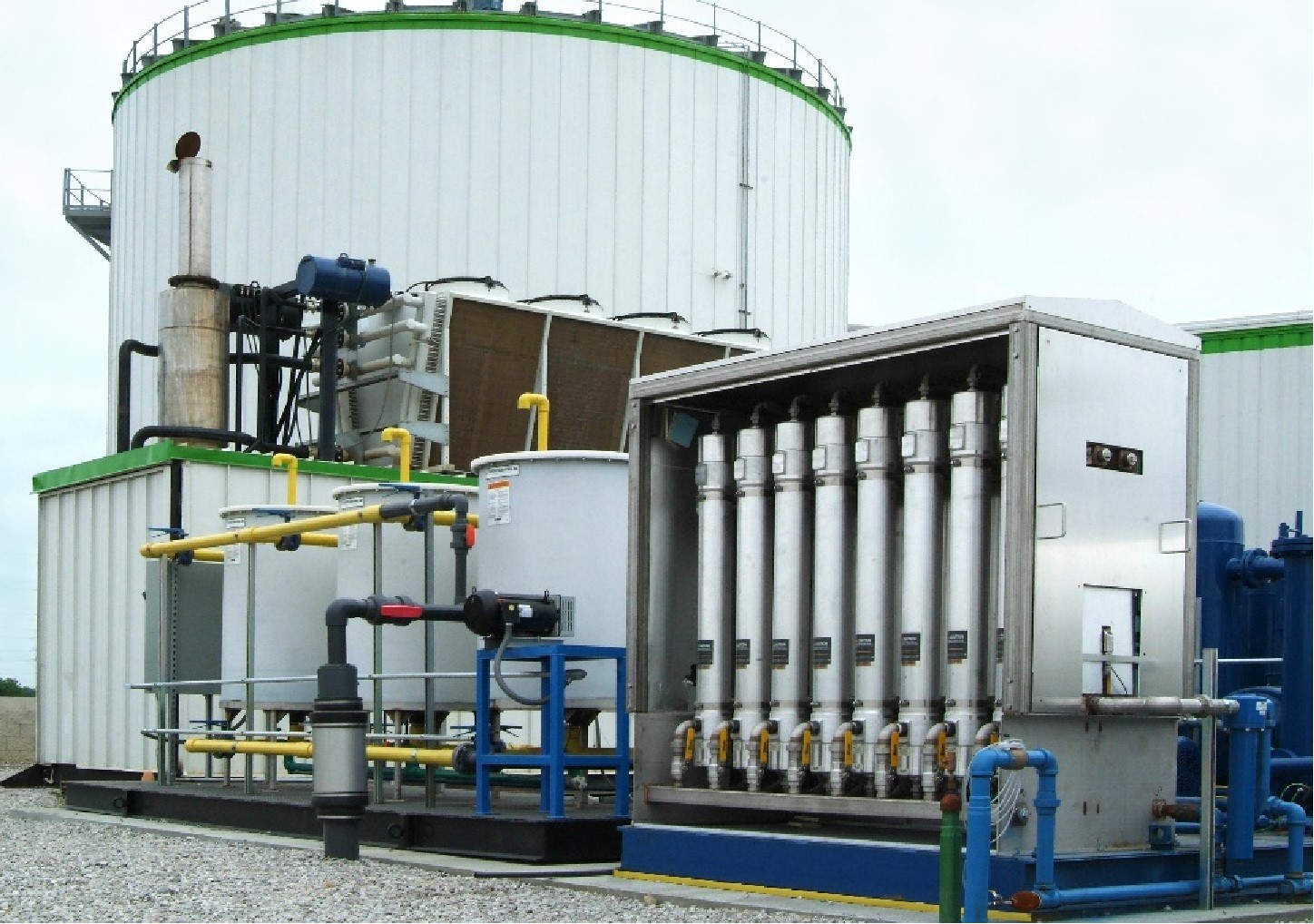
Selecting the appropriate separation technology forms the foundation of any purification project. Four primary methods dominate the current industrial landscape, each with distinct operational characteristics and output quality profiles.
Pressure Swing Adsorption (PSA)
PSA systems employ adsorbent materials such as activated carbon or zeolites to selectively retain CO₂ and other impurities under high pressure. Regeneration occurs through pressure reduction, allowing continuous cycling. Modern PSA units achieve methane recoveries above 96% while maintaining CO₂ slip below 2%.
Membrane Separation
Polymeric or ceramic membrane modules separate gases based on differential permeation rates. CO₂, water vapor, and hydrogen sulfide permeate preferentially, leaving a methane-rich retentate stream. Membrane systems operate with minimal moving parts and offer rapid start-stop capabilities, making them suitable for variable feed flows.
Water Scrubbing
This physical absorption process leverages the higher solubility of CO₂ and H₂S in water compared to methane. Pressurized water cascades through a packed column, removing acid gases, while dissolved methane is recovered through flash tank degassing. Water scrubbing remains a popular choice in agricultural biogas installations due to its simplicity and use of non-toxic media.
Amine Scrubbing (Chemical Absorption)
Amine solutions, typically monoethanolamine or methyldiethanolamine, chemically bind CO₂ and H₂S. The rich solvent is heated in a regeneration column to release the acid gases, producing a high-purity methane stream with less than 1% CO₂. Amine systems deliver exceptionally low outlet CO₂ concentrations but require careful thermal management and corrosion control.
Gas Quality Parameters and Performance Metrics
End-use applications dictate the required purity levels. For biomethane to be injected into natural gas grids in most jurisdictions, methane content must exceed 96% with total sulfur below 5 ppm, and siloxane concentrations below 0.1 mg/Nm³. A properly designed biogas purification plant monitors these parameters continuously:
Methane concentration – typically measured online via non-dispersive infrared (NDIR) sensors.
Wobbe index – a critical indicator of interchangeability with natural gas.
Dew point temperature – maintained below -10°C to prevent condensate formation in distribution networks.
Particulate load – post-polishing filtration ensures particles are reduced to < 1 µm.
These parameters are not static; feed gas composition varies with feedstock type and digester conditions. A robust control architecture adjusts process variables such as pressure, temperature, and purge flow to maintain product specifications throughout the operational envelope.
Application Environments and Integration Scenarios
The configuration of a biogas purification plant is heavily influenced by the end-use case. Three broad categories cover the majority of industrial installations.
Grid Injection Stations
These facilities are typically located adjacent to natural gas transmission pipelines and operate at high capacity (1,000+ Nm³/h). Gas quality must comply with national grid codes, which often include strict odorization, calorific value, and carbon footprint requirements. Purification plants in this segment commonly use PSA or amine scrubbing combined with gas conditioning systems for pressure regulation and odorant injection.
Vehicle Fuel (CBG/LBG)
Compressed biomethane (CBG) or liquefied biomethane (LBG) for transportation demands the highest purity – often 97–99% methane with negligible trace components. Membrane or hybrid systems (membrane + PSA) are frequently deployed here, as they provide the flexibility to achieve ultra-high purity without the thermal degradation risks associated with amine solvents.
On-Site Power Generation
While less stringent than grid or vehicle fuel specifications, biogas-fuelled combined heat and power (CHP) units still require hydrogen sulfide and siloxane removal to protect engine components. A compact purification plant integrated with the CHP skid reduces maintenance intervals and improves overall electrical efficiency.
Operational Challenges and Engineering Solutions
Despite the maturity of the underlying technologies, operators of biogas purification plant frequently encounter issues that can degrade performance or increase downtime.
Siloxane fouling – these silicon-based compounds deposit on membrane surfaces and adsorbent beds, progressively reducing separation efficiency. Activated carbon filters placed upstream of the main separation unit provide effective protection, with replacement cycles determined by the siloxane loading in the raw gas.
Methane slip during regeneration – PSA and amine systems lose a fraction of methane during the regeneration step. Implementing a variable purge control strategy, where purge flow is modulated based on feed composition, can reduce methane slip from 3–5% down to 1.5–2.5%.
Corrosion due to acid gases – wet biogas containing CO₂ and H₂S forms carbonic and sulfuric acids. Specifying corrosion-resistant alloys (e.g., 316L stainless steel) for wetted parts and installing knockout drums to remove entrained moisture before gas reaches the upgrading section mitigate this risk.
Frequent activated carbon replacement – the adsorption capacity of carbon beds is finite and dependent on the concentration of volatile organic compounds (VOCs) and sulfur species. Implementing a staged filtration approach, where bulk H₂S is removed by iron-impregnated media before carbon polishing, extends carbon lifetime by 40–60%.
Each of these challenges is addressed through a combination of design choices, operational procedures, and predictive maintenance protocols. For instance, online gas chromatographs can provide early warning of membrane degradation, allowing scheduled membrane replacement before product quality falls out of specification.
System Integration and Balance of Plant
A biogas purification plant does not operate in isolation. The integration with upstream digestion units and downstream compression/storage systems requires careful hydraulic and electrical coordination. Key integration points include:
Biogas buffering and pressure regulation – a buffer tank with a capacity equivalent to 2–4 hours of normal production smooths fluctuations from the digester. Pressure regulators ensure the feed pressure remains within the optimal operating window of the upgrading unit (typically 6–10 barg for PSA).
Thermal management – water scrubbing and amine units generate heat during solvent regeneration; this thermal energy can be partially recovered to pre-heat the feed gas or to maintain digester temperatures, improving overall plant thermal efficiency.
Flare or thermal oxidizer – off-gases from the purification process (CO₂-rich permeate or tail gas) often retain 5–10% methane. An enclosed flare or catalytic oxidizer ensures that these residual hydrocarbons are oxidized, meeting environmental regulations while minimising odour issues.
The mechanical and control integration is typically delivered as a turnkey solution, where the supplier assumes responsibility for the entire engineering, procurement, and commissioning scope. This approach reduces project risk and guarantees a single point of accountability for performance.
Environmental Footprint and Energy Balance
The sustainability of a biogas purification plant is determined not only by the methane recovery rate but also by the parasitic energy consumption. Compression, liquid circulation pumps, and regeneration heaters represent the main electrical and thermal loads. Typical plant auxiliary power consumption ranges from 0.15 to 0.25 kWh/Nm³ of raw biogas processed. Innovations such as mechanical vapour recompression for amine regenerators and energy-efficient turbo-compressors are gradually reducing this figure. Additionally, the captured CO₂ stream can be utilised in greenhouses or carbonated beverage production, further improving the life-cycle environmental performance.
Regulatory Framework and Certification
Biomethane produced in a certified biogas purification plant must comply with national and regional standards. In Europe, the EN 16723 series specifies requirements for biomethane injection into natural gas networks and for use as transport fuel. North American installations reference ASTM D8086-16 for pipeline-quality biomethane. Certification bodies such as ISCC and SCS Global provide independent verification of sustainability criteria, including greenhouse gas emission reductions. These regulatory aspects influence instrumentation choices, documentation, and operational reporting – all of which must be factored into the plant design from the concept phase.
Frequently Asked Questions
Q1: What is the typical methane recovery rate of a modern biogas purification plant?
A1: State-of-the-art plants achieve methane recoveries between 96% and 98.5%, depending on the technology and the raw biogas composition. PSA systems with multi-bed configurations tend to operate at the upper end of this range, while membrane-only systems may achieve slightly lower recoveries but with simpler maintenance.
Q2: How does the presence of oxygen or nitrogen in biogas affect purification?
A2: Oxygen and nitrogen act as non-condensable inert gases that pass through most upgrading units and accumulate in the product stream. For grid injection, oxygen is typically limited to 0.5–1% to prevent corrosion in pipelines. Nitrogen dilution reduces the calorific value, so feed gas with high nitrogen content (from air ingress in digesters) often requires additional treatment, such as membrane cascades or cryogenic distillation, which adds complexity.
Q3: What maintenance schedule is recommended for a biogas purification plant?
A3: Maintenance intervals depend on the technology and the contaminant load. For PSA plants, adsorbent replacement is typical every 8–10 years, with valve servicing every 2–3 years. Membrane elements have a service life of 5–7 years, while activated carbon beds for VOC and siloxane removal are replaced every 6–18 months based on online breakthrough monitoring. A well-defined preventive maintenance plan, aligned with the manufacturer's recommendations, ensures high availability (typically > 95%).
Q4: Can a biogas purification plant handle variable feed flow rates?
A4: Yes, but with certain constraints. PSA and membrane systems tolerate flow fluctuations of ±20% without significant performance degradation, provided the control system adjusts cycle times or membrane feed pressures accordingly. Water and amine scrubbing units are less flexible; their internal hydraulic and mass transfer characteristics are optimised for a specific flow range. For highly variable biogas production (common in farm-based digesters), a buffer vessel combined with a flow-averaging control loop is strongly advised.
Q5: Are there specific requirements for the gas compression system downstream of purification?
A5: The compressed biomethane must meet the intake pressure requirements of the gas grid or the refuelling station. For grid injection, compressors typically discharge at 20–40 barg; for vehicle fuelling, pressures of 200–250 barg are needed for Type IV cylinders. The compression system must incorporate after-coolers and condensate separation to remove any residual moisture, and a final particulate filter (0.01 µm) is recommended to protect downstream equipment from abrasion.
For project-specific engineering support, performance guarantees, and tailored plant designs that address your feedstock and end-use requirements, contact our technical sales team to schedule a feasibility review and obtain a preliminary process flow diagram for your application.