


News
We'll get back to you as soon as possible.
5 Engineering Benchmarks for High-Purity PSA Biogas Upgrading Systems
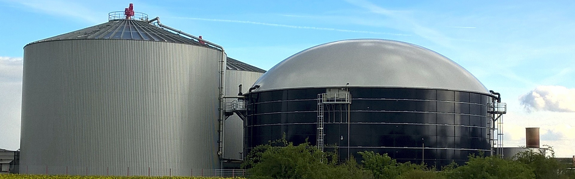
Raw biogas produced via anaerobic digestion of agricultural residues, wastewater sludge, and organic municipal waste represents a primary foundation for renewable fuels. Untreated biogas primarily comprises methane (50% to 65% CH4) and carbon dioxide (35% to 50% CO2), saturated with water vapor and contaminated with trace hydrogen sulfide (H2S), siloxanes, and volatile organic compounds (VOCs). Converting this intermediate fuel into pipeline-grade biomethane or compressed bio-natural gas (bio-CNG) requires the selective removal of non-combustible and corrosive fractions. Among commercial gas separation technologies, industrial facilities continuously deploy psa biogas upgrading systems to achieve methane concentrations exceeding 97% while eliminating wet chemical effluents.
Molecular Separation Fundamentals and Adsorption Mechanics
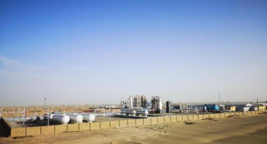
Pressure Swing Adsorption operates on the differential physical affinity between specific gas molecules and a microporous solid adsorbent under varying partial pressures. In raw biogas mixtures, the target is separating carbon dioxide from methane without causing chemical transformations or generating hazardous spent solvents.
The separation mechanism primarily relies on kinetic selectivity rather than equilibrium capacity alone. Adsorbent media typically feature precisely engineered pore dimensions tailored to exploit the slight differences in molecular geometry between the target and waste gases.
Kinetic Diameter Differential: Carbon dioxide exhibits a kinetic diameter of approximately 0.33 nm, whereas methane measures approximately 0.38 nm.
Diffusion Rates: Because the smaller carbon dioxide molecule diffuses through narrow pore networks several orders of magnitude faster than methane, the solid matrix preferentially captures CO2 during brief pressurized exposure windows.
Sorbent Matrix: Carbon Molecular Sieves (CMS) serve as the primary medium for this separation, though certain synthetic zeolites (such as 13X or 4A) are utilized when targeting specific equilibrium-driven separations or secondary polishing phases.
CMS manufacture involves thermal cracking and controlled pore constriction of carbonaceous precursors, yielding an internal surface area that can exceed 1,000 m²/g. Under pressure, CO2 enters the narrow micropores and is retained within the internal matrix. Methane, possessing higher steric hindrance and slower mass transfer rates, passes through the adsorbent bed relatively unhindered, emerging at the column discharge as high-purity biomethane.
Column Cycling and Multi-Bed Architecture
Batch-mode adsorption cannot support continuous industrial flows. Industrial installations implement multi-column configurations—typically ranging from four to eight interconnected vessels—operating out of phase through precise valve sequences. This arrangement ensures steady product flow and limits methane losses during bed regeneration.
1. Adsorption (Pressurization Stage)
Pre-conditioned biogas enters the bottom of the active column at typical operating pressures between 4 barg and 9 barg. As the gas travels upward through the packed CMS bed, CO2 molecules selectively enter the micropores. The high-purity methane stream exits the top of the vessel, monitored continuously by downstream thermal conductivity detectors or nondispersive infrared (NDIR) analyzers for methane purity.
2. Pressure Equalization (Energy and Gas Conservation)
Before the mass transfer zone reaches the column exit (which would cause CO2 breakthrough into the product line), feed flow to the saturated bed stops. To preserve the energy expended during compression and to recover void-space methane, the pressurized vessel is connected directly to a depressurized vessel awaiting re-pressurization. Gas transfers rapidly between columns until pressures equilibrate, directly retaining a substantial volume of methane without secondary mechanical compression.
3. Blowdown (Counter-Current Depressurization)
Following equalization, the saturated column vents counter-currently to atmospheric pressure. The sharp drop in CO2 partial pressure destabilizes the physical bonds holding the adsorbed molecules to the CMS pore walls. Carbon dioxide desorbs from the internal surface and vents via the bottom manifold as a concentrated off-gas stream.
4. Low-Pressure Purge
Desorption cannot reach full regeneration under atmospheric venting alone due to residual partial pressures. A small slipstream of upgraded biomethane (or clean product gas from an adjacent operating column) sweeps counter-currently through the CMS bed at near-atmospheric pressure. This sweep lowers the CO2 partial pressure to zero, driving remaining adsorbed contaminants out of the microscopic pores and restoring baseline adsorption capacity.
5. Repressurization
Once purged, the bed must return to system operating pressure before re-admitting feed gas. Repressurization occurs in two stages: first through gas equalization with a freshly saturated bed, followed by back-filling with methane product gas or incoming compressed feed. Gradual pressure rebuilding prevents fluidization of the CMS granules, which could otherwise cause mechanical attrition and bed channeling.
Pre-Treatment Requirements for PSA Biogas Upgrading
Adsorbent performance depends on the purity of the incoming gas stream. Feed gas entering a psa biogas upgrading unit must meet strict quality standards to prevent irreversible fouling of the Carbon Molecular Sieve structure. Industrial systems incorporate dedicated upstream conditioning skids to eliminate contaminants before the adsorption stage.
Hydrogen Sulfide (H2S) Abatement: High concentrations of H2S irreversibly poison standard CMS materials by reacting within narrow pore necks and degrading surface volume. Upstream bulk desulfurization (using biological scrubbers or chemical iron sponges) combined with secondary lead-lag impregnated activated carbon vessels reduces H2S levels below 1 ppm.
Moisture and Aerosol Coalescence: Raw biogas leaves digesters at relative humidity. Water molecules compete aggressively with CO2 for adsorption sites and cause physical breakdown of CMS binders. Upstream conditioning requires industrial chillers to drop the gas dew point to 3°C to 5°C, followed by mechanical droplet separators and desiccant dryers.
Siloxane and VOC Extraction: Anaerobic digestion of organic municipal waste generates cyclic and linear volatile methyl siloxanes alongside aromatic hydrocarbons (BTEX). These high-molecular-weight compounds condense inside micropores, causing permanent blind spots on the adsorbent. Guard beds packed with regenerable or sacrificial deep-bed activated carbon capture these contaminants ahead of the main separation vessels.
Comparative Analysis: PSA Biogas Upgrading vs. Membrane and Scrubbing Technologies
Selecting appropriate gas upgrading systems requires evaluating mechanical simplicity, consumable usage, and operational footprints. Plant operators evaluating psa biogas upgrading versus amine wash or water scrubbing systems identify distinct operational attributes that define long-term plant stability.
Water scrubbing relies on high-pressure water dissolving CO2 physically, demanding continuous supplies of clean process water and biocides to prevent internal biological growth. Amine systems utilize thermal energy to break chemical bonds between CO2 and liquid reagents (such as monoethanolamine or methyldiethanolamine). While amine plants achieve low methane slip, they generate toxic chemical waste streams and require steady access to industrial heat sources.
Polymeric membranes separate gases based on permeability differences across hollow-fiber bundles. Membranes operate continuously without cyclic valve actuation, but they require high feed pressures (frequently 12 to 16 barg) and run high replacement costs when polymeric structures foul from oil aerosols or trace VOC breakthrough. PSA systems utilize entirely dry separation mechanics, demand zero external process heat, require no hazardous liquid disposal, and operate effectively on moderate feed pressures, simplifying ongoing regulatory compliance.
Mitigating Methane Slip and Emission Controls
Single-stage adsorption systems experience an inherent methane loss, known as methane slip, typically ranging between 1.5% and 3.5% of the total feed methane. This slip occurs because some methane remains trapped within bed void spaces and is swept into the exhaust stream during blowdown and purge cycles. In modern facilities, this exhaust cannot be vented untreated due to greenhouse gas regulations.
To eliminate these environmental losses, modern system design implements secondary recovery stages or exhaust gas abatement modules:
Two-Stage PSA Integration: The desorption tail gas, containing up to 10% methane along with high concentrations of CO2, passes to a secondary, smaller PSA unit. This secondary bed concentrates the residual methane and routes it back into the primary feed inlet, raising overall plant recovery efficiency past 98.5%.
Vacuum Pressure Swing Adsorption (VPSA): Incorporating mechanical vacuum pumps during the desorption stage reduces reliance on high-volume purge gas. Pulling deep vacuum (-0.8 barg) strips adsorbed CO2 without wasting valuable product biomethane as a sweep medium, directly lowering methane slip.
Regenerative Thermal Oxidizers (RTO): Tail gases with residual traces of unrecovered methane pass through an RTO or catalytic oxidation unit. The system oxidizes remaining volatile hydrocarbons flamelessly, converting trace slip into energy neutral CO2 and H2O before atmospheric discharge.
Valve Automation and Skid Engineering Specifications
Because cycling vessels switch stages every 60 to 180 seconds, the mechanical reliability of automated process valves directly determines overall system availability. A six-column facility cycles its primary control valves hundreds of thousands of times annually.
Industrial skids utilize high-cycle pneumatic butterfly or ball valves equipped with hardened metal seats, high-integrity stem packings, and swift-acting double-acting actuators. Soft-seated valves are avoided in high-pressure drop positions due to seal erosion from rapid micro-channelling. Automated valve travel feedback connects directly to high-reliability programmable logic controllers (PLCs), verifying precise seal timing before the system advances to subsequent cycle stages.
Flow distributors at the top and bottom of each pressure vessel prevent gas jetting from disturbing the adsorbent bed. Support grids, ceramic ball under-beds, and heavy-duty mechanical hold-down plates retain the CMS under dynamic pressure swings, avoiding localized fluidization and media pulverization over years of base-load duty.
Feedstock Variability and Wobbe Index Compliance
Biogas plants process fluctuating substrate mixtures over time. Digesters shifting from animal manure to food waste generate sudden spikes in CO2 volume alongside shifting VOC profiles. Maintaining strict biomethane quality despite dynamic feed inputs requires automated cycle modulation within the upgrading skid.
Transmission pipelines dictate stringent parameters for Wobbe Index, Higher Heating Value (HHV), oxygen content, and moisture dew point. When upstream CO2 levels climb, static valve timings may lead to out-of-specification gas reaching the grid injection unit. Advanced control loops counter this by measuring inlet mass flow and bed exit composition continuously, automatically varying cycle step times to maintain the required separation profile.
If biomethane fails downstream compliance tests, rapid-switching rejection valves redirect the off-spec product gas back to the digester gas holder or raw gas buffer vessel. This closed-loop diversion safeguards transmission networks against off-spec gas without venting methane to the atmosphere.
Project Sizing and Industrial Implementation Guidelines
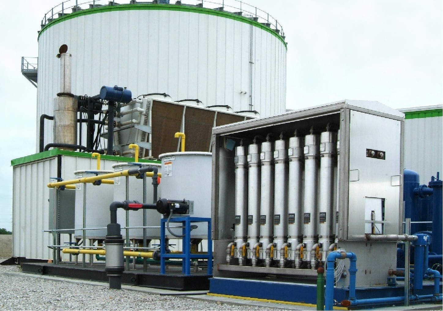
Correctly sizing and specifying capacity for psa biogas upgrading equipment requires thorough evaluation of raw gas profiles across seasonal digester operational cycles. Oversizing columns results in prolonged cycle times that reduce separation efficiency, whereas undersizing units causes excessive gas velocity, bed fluidization, and early CO2 breakthrough.
Engineers evaluating site development must document key boundary parameters:
Minimum, average, and peak raw gas volume flows calculated in standard cubic meters per hour (Nm³/h).
Comprehensive chromatographic gas analysis identifying baseline CO2, O2, N2, and H2S concentrations alongside seasonal ranges.
Contaminant profiling for siloxanes (D4, D5, D6), organic halides, and total VOCs.
Available electrical supply capacity for primary feed gas compression and subsequent high-pressure grid injection compressors.
Downstream delivery requirements, comparing low-pressure local distribution grids (typically 4 to 8 barg) against regional high-pressure gas transmission networks (typically 40 to 80 barg).
Establishing these parameters early ensures the Carbon Molecular Sieve volume, valve manifolds, blowdown vessels, and pre-treatment absorption trains operate within verified thermodynamic thresholds over the plant's operational lifespan.
Initiate Your Biogas Upgrading Project
Deploying an industrial-scale renewable gas plant requires robust separation engineering tailored to your feedstock profiles, plant capacities, and injection standards. Submit your raw gas analytical profiles and target delivery parameters to our engineering team to receive a comprehensive mass-balance evaluation, system skid layout, and detailed equipment proposal for your site.
Frequently Asked Questions
Q1: What is the typical operational lifetime of Carbon Molecular
Sieve (CMS) in these upgrading systems?
A1: Under proper operating
conditions with rigorous upstream pre-treatment to intercept moisture, H2S, and
heavy hydrocarbons, high-grade CMS exhibits an operational lifetime of 8 to 10
years without noticeable degradation in adsorption selectivity.
Q2: Can this separation process remove nitrogen and oxygen present in
raw biogas?
A2: Standard kinetic CMS focuses primarily on CO2
removal. Because oxygen (0.346 nm) and nitrogen (0.364 nm) have molecular sizes
close to CO2 and methane, standard single-stage kinetic beds cannot completely
strip them. When significant air ingress occurs, specialized secondary
adsorbents or catalytic deoxo systems are integrated downstream.
Q3: What electrical consumption figures are associated with this
separation methodology?
A3: The process itself is driven entirely by
pressure changes and automated valving. Electrical draw is primarily determined
by the raw gas compressor boosting biogas to adsorption pressure, typically
ranging between 0.20 kWh and 0.30 kWh per normal cubic meter (Nm³) of raw gas
treated.
Q4: How does ambient temperature affect adsorption column
efficiency?
A4: Physical adsorption is an exothermic process; higher
temperatures reduce the adsorption capacity of porous carbon matrices.
Facilities operating in high ambient environments incorporate feed gas
after-coolers to ensure gas enters the columns at stable temperatures, generally
between 15°C and 25°C, to preserve separation performance.
Q5: What is the standard methane purity achieved by this technology
without secondary enrichment?
A5: Commercial units routinely
generate biomethane with methane purity between 96% and 99% CH4, easily
satisfying the technical criteria for natural gas grid injection and vehicle
fuel (CNG) standards worldwide.