


News
We'll get back to you as soon as possible.
4 Core Technologies Powering a High-Yield Paddy Straw Biogas Plant
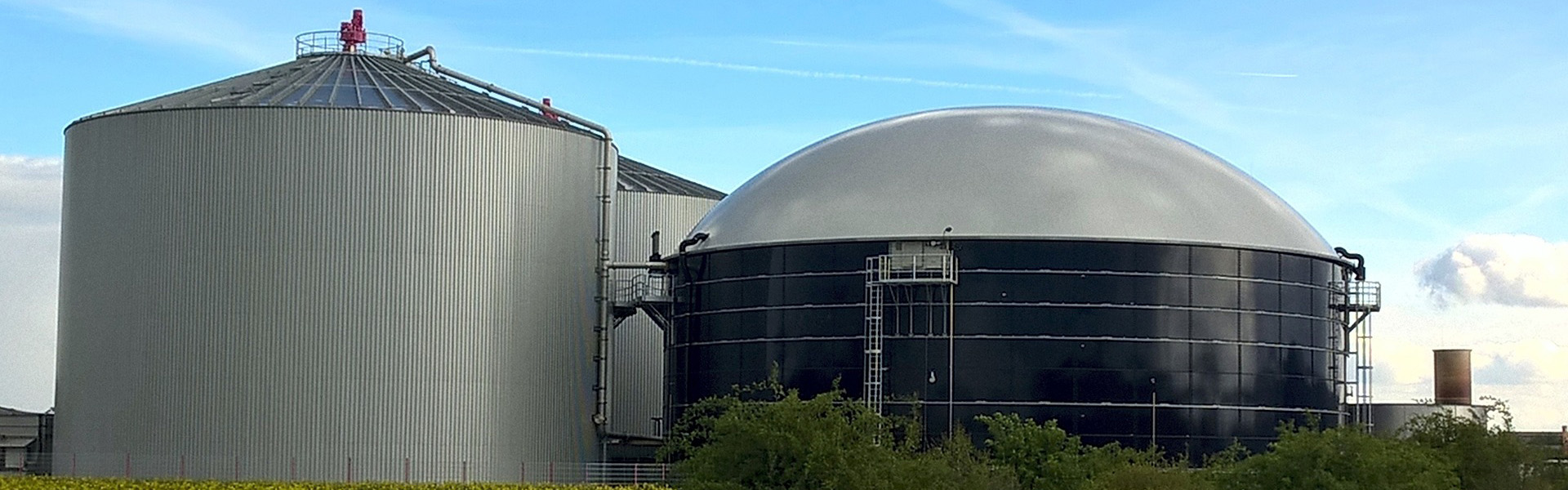
Agricultural crop residues represent an abundant, carbon-rich substrate for renewable natural gas generation. Among these materials, rice crop residue features distinct chemical and physical complexities. Establishing a commercial-scale paddy straw biogas plant requires addressing lignocellulosic recalcitrance, high ash fractions, and high carbon-to-nitrogen ratios. Processing these stalks into biomethane requires robust pre-treatment assemblies, specialized digestion tank architectures, and selective gas separation units configured to handle tough straw matrices.
Biochemical Structure and Feedstock Characteristics
Paddy straw is a rigid lignocellulosic composite composed of cellulose, hemicellulose, and lignin. Cellulose microfibrils form a structured crystalline core shielded by amorphous hemicellulose polymers and bound by an outer lignin sheath. Lignin functions as a natural barrier against enzymatic hydrolysis, resisting breakdown during conventional anaerobic digestion stages.
Beyond the structural biopolymers, rice stalks absorb significant amounts of monomeric silicic acid from wetland soils, depositing it as amorphous silica within epidermal cell walls. This silica content accounts for 10% to 17% of total inorganic ash. In continuous wet processing streams, abrasive silica accelerates mechanical wear across pipeline bends, cutting assemblies, pump impellers, and internal heat exchanger jackets.
The raw carbon-to-nitrogen (C:N) ratio of rice residue ranges between 60:1 and 80:1. Methanogenic archaea operate at peak metabolic rates when feeding on an organic blend showing a C:N ratio between 25:1 and 30:1. Unbalanced carbon loads exhaust accessible nitrogen reserves, stalling volatile fatty acid consumption and causing system acidification. Balancing this operational parameter involves co-digesting the straw with animal slurries, municipal biosolid cakes, or controlled additions of industrial urea and liquid ammonia solutions.
Feedstock Disruption and Hydrolysis Enhancement
Hydrolysis is the rate-limiting step in anaerobic systems using straw. Direct digestion of raw chopped stalks yields poor volatile solids destruction and produces floating crust layers inside the digesters. Industrial facilities employ structured pre-treatment operations to expose the inner carbohydrate polymers before feeding the primary reactors.
Mechanical size reduction represents the baseline physical intervention. Multi-stage shredders, hammer mills, and high-shear extruders tear straw fibers apart, decreasing particle sizes below 10 millimeters while increasing specific surface area. Mechanical extrusion applies intense physical compression and shear forces, generating micro-fissures through the tough outer sheath. This shear promotes immediate hydration upon contact with water or liquid recirculate.
Thermal hydrolysis units subject shredded straw slurries to saturated steam environments at temperatures ranging from 140°C to 180°C under elevated pressures. Instantaneous pressure releases, commonly known as steam explosion, vaporize internal moisture. This structural expansion strips away hemicellulose bonds and disrupts the outer lignin matrix. Implementing these mechanical and thermo-chemical stages enables a modern paddy straw biogas plant to achieve volatile solids conversion rates exceeding 70% within shortened hydraulic retention times.
Biochemical conditioning strategies utilize targeted hydrolytic enzyme cocktails to supplement mechanical disruption. Cellulases, endo-glucanases, and xylanases attack exposed carbohydrate complexes, converting insoluble fibers into soluble monosaccharides and oligosaccharides. Introducing these enzymes into dedicated conditioning vessels accelerates methane generation kinetics inside downstream methanogenic digestors.
Digester Hydraulics, Agitation, and Process Stabilization
The low bulk density of dry straw causes chopped fibers to float on liquid substrates, forming persistent surface scums. Without purposeful agitation and fluid control, these floating layers thicken, trap gas bubbles, impede mass transfer, and foul gas off-take pipes. Tank design must incorporate robust mixing solutions suited for non-Newtonian, high-viscosity slurries.
Continuous Stirred Tank Reactors (CSTR): These vessels utilize central top-mounted vertical mixers, low-speed angled impellers, or high-torque horizontal paddle agitators. Multi-level impeller systems create complete fluid movement that pulls floating fibers down into the active digestion zone while preventing dense silica sand from settling on the tank floor.
Plug Flow Digesters: Designed for high-solids feeds containing 15% to 22% dry matter, plug flow tanks advance material horizontally through an elongated channel. Agitator paddles rotate perpendicular to flow lines, blending new feed with active methanogenic digestate while off-gassing raw methane smoothly along the transit path.
Multi-Stage Digestion Configurations: Separating the acidogenic-acetogenic stages from the terminal methanogenic stage preserves chemical stability. Dedicated acid hydrolysis tanks operate at slightly acidic conditions between pH 5.5 and 6.5, solubilizing complex starches and carbohydrates. The resulting liquor feeds an anaerobic reactor held at neutral conditions between pH 7.2 and 7.8, protecting methanogenic communities from rapid organic shocks.
Continuous operational surveillance tracks volatile fatty acids relative to total inorganic carbon (FOS/TAC ratio). Ratios kept between 0.2 and 0.3 confirm healthy microbial populations. Deviations above 0.4 indicate incoming hydraulic overloads or micro-nutrient deficiencies, requiring reduced feed inputs and supplemental dosing of trace elements like cobalt, nickel, molybdenum, and selenium to support methanogenic enzymes.
Raw Gas Treatment and Contaminant Removal
Crude biogas leaving an agricultural paddy straw biogas plant contains methane, carbon dioxide, moisture, and hazardous impurities. While paddy straw generates lower hydrogen sulfide concentrations than animal manures, sulfur compounds remain present alongside residual siloxanes, nitrogen traces, and microscopic particulates.
High-efficiency cooling systems remove bulk water vapor from the warm, saturated biogas. Refrigerated gas chillers lower vapor temperatures below dew points, condensing moisture that is continuously discharged through automatic drains. Particulate filters installed along the processing run catch airborne fiber fragments and fine abrasive mineral dust before gas reaches rotary blowers and compressors.
Biogas desulfurization systems protect downstream upgrading systems from sulfur-induced corrosion and catalyst poisoning. Chemical scavenging towers, impregnated activated carbon beds, and biological trickling filters serve as primary desulfurization options. Biological trickling filters culture sulfur-oxidizing bacteria on specialized carrier media, oxidizing gaseous hydrogen sulfide into sulfate solutions using controlled air injection, eliminating recurring chemical consumable needs.
Biomethane Upgrading Methodologies
Purifying crude methane to renewable natural gas (RNG) or compressed biomethane (CBG) standards requires separating carbon dioxide. Gas specifications for commercial pipeline delivery or vehicle fuel demand methane purities between 96% and 99%, with carbon dioxide levels restricted below 2%.
Polymeric hollow-fiber membrane systems offer flexible gas upgrading solutions. Operating on selective permeation principles, gas molecules move across specialized polymeric walls under pressure. Carbon dioxide, moisture, and hydrogen sulfide permeate rapidly, while methane remains within the high-pressure stream. Three-stage membrane configurations recirculate permeate streams, keeping overall methane recovery above 99.2% without requiring heat inputs.
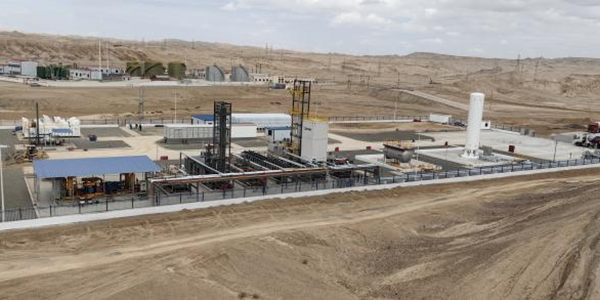
Pressure Swing Adsorption (PSA) separates gas molecules under pressure based on molecular size and structural characteristics. Passing raw gas through vertical vessels packed with carbon molecular sieves retains carbon dioxide, moisture, and oxygen, letting pure methane flow through the outlet. Depressurizing the bed releases the trapped carbon dioxide, regenerating the adsorbent material. PSA systems operate efficiently under variable raw gas compositions and flow rates.
Water scrubbing utilizes carbon dioxide's higher solubility in water compared to methane at elevated pressures. Biogas enters the bottom of a tall absorption column while pressurized cold water rains down from the top. The water absorbs the carbon dioxide, discharging clean biomethane from the column summit. The loaded effluent transfers to a stripping column where pressure drops release the dissolved carbon dioxide, allowing water recycling through closed treatment loops.
Digestate Beneficiation and Sustainable Nutrient Loops
Operating a continuous agricultural digestion plant generates substantial volumes of organic effluent. Efficient post-digestion separation divides bulk discharge into solid fiber cakes and nutrient-rich liquid fractions. Screw presses, vibrating screens, and continuous decanter centrifuges separate this wet stream effectively.
The solid digestate fraction, rich in stabilized carbon and residual silica, serves as a conditioning organic compost. Applying this solid material back to farming plots replenishes natural topsoils, improves moisture retention in sandy soils, and returns plant silica to strengthen future rice stems against pests. Industrial composting facilities blend these solids with leaves and forestry scraps, generating bagged organic fertilizers for commercial sale.
Liquid digestate contains dissolved ammonium, potassium, and trace minerals. Stored in covered lagoons or dynamic buffer tanks, this liquid works well as liquid bio-fertilizer for surrounding crop fields via drip irrigation networks. Alternatively, treating this liquid through reverse osmosis and ultrafiltration systems recovers clear process water, minimizing fresh water intake across the facility.
Process Integration and Plant Architecture
Designing an industrial paddy straw biogas plant involves harmonizing front-end raw material handling with back-end upgrading systems. Because rice harvesting happens in brief seasonal windows, plant yards need organized storage layouts. Dry bale yards must protect stockpiled straw from moisture, spontaneous microbial heating, and ambient moisture uptake using dry storage sheds, tarp covers, and automated fire monitoring networks.
Internal energy balances determine total facility production yields. Combined Heat and Power (CHP) units or dual-fuel biogas boilers supply hot water to maintain mesophilic (38°C to 40°C) or thermophilic (52°C to 55°C) digester temperatures. Implementing variable frequency drives across high-load pumps, agitators, and compressor motors reduces parasite electrical loads throughout continuous operations.
Automated SCADA frameworks integrate multi-point plant data, monitoring tank pressures, slurry levels, methane percentages, and oxygen values. Automated mass flow controllers modulate raw feed delivery dynamically, adjusting feed rates according to instantaneous biogas composition changes. Automated isolation valves and continuous flare stacks manage emergency bypass events, maintaining continuous process safety without venting unburned methane into the atmosphere.
Project Sizing, Equipment Specifications, and Technical Support
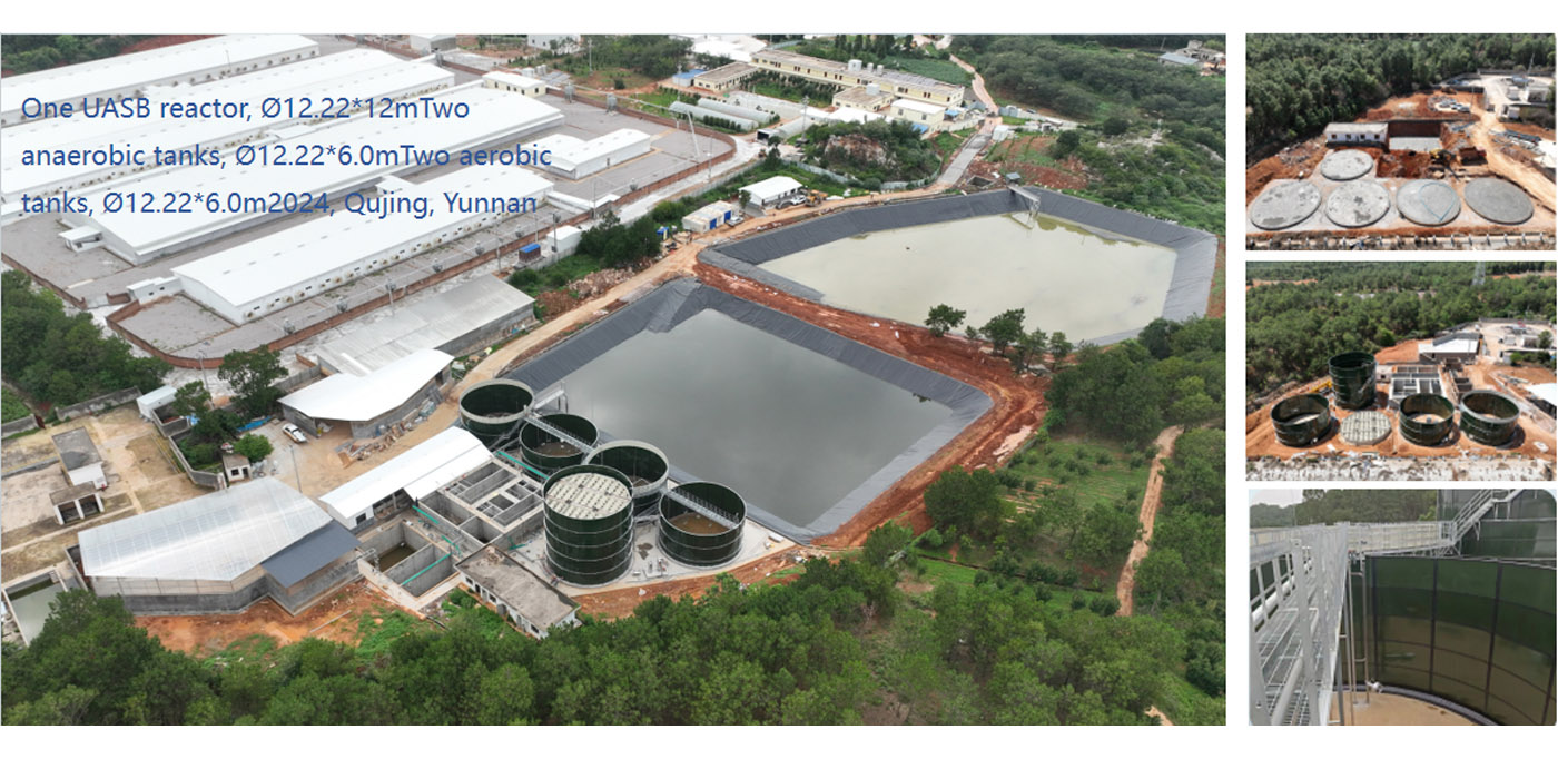
Constructing a dependable paddy straw biogas plant requires targeted engineering expertise, matched components, and experienced industrial execution. Feedstock parameters, available daily tonnages, transport footprints, and regional biomethane sales specifications govern plant equipment selection. Tailored anaerobic digestion modules, optimized pre-treatment packages, and dedicated membrane separation skids are designed to process straw materials reliably.
Our engineering group designs, manufactures, and commissions integrated biomethane processing plants configured for agricultural and industrial waste conversions. Contact our engineering team to review raw material characteristics, digester tank sizes, downstream purification skids, and project designs matching your project goals.
Frequently Asked Questions
Q1: What is the typical biomethane yield from an operational paddy straw biogas plant?
A1: Methane yields depend on harvest maturity,
storage conditions, and pre-treatment methods. High-efficiency systems using
chemical-mechanical or thermal pre-treatment generate between 180 and 260 normal
cubic meters of biogas per dry ton of straw, maintaining methane concentrations
between 50% and 58% before upgrading.
Q2: Why does silica pose continuous problems when running rice straw
anaerobic systems?
A2: Rice straw absorbs high concentrations of
silicic acid, generating abrasive mineral silica within its tissue. Suspended in
moving slurries, silica abrades chopper knives, pump impellers, and pipe elbows.
Without designated sediment traps, silica settles in digester bottoms, reducing
active reactor volumes over operational years.
Q3: Is mono-digestion of rice straw feasible at industrial
scales?
A3: Mono-digestion is technically viable if operators
address nitrogen imbalances and micronutrient limits. Feeding pure straw
requires adding urea, ammonium compounds, or recycled liquid digestate to lower
the high C:N ratio into the balanced 25:1 to 30:1 range, accompanied by regular
dosing of trace elements like nickel, cobalt, and selenium.
Q4: How does pre-treatment improve digestion kinetics for straw
substrates?
A4: Lignin sheaths protect cellulose and hemicellulose
fibers from hydrolytic bacteria. Pre-treatment steps—such as mechanical
extrusion, steam explosion, or enzymatic exposure—break down these barriers,
opening accessible carbohydrate surfaces and cutting overall hydraulic retention
times inside the primary digester tanks.
Q5: What standard of gas purity can upgrading systems
deliver?
A5: Membrane separation and modern PSA plants generate
biomethane purities between 97% and 99% methane. These systems remove carbon
dioxide, hydrogen sulfide, and trace moisture, meeting injection specifications
for local gas distribution utilities or regional compressed vehicle fuel
grids.