


News
We'll get back to you as soon as possible.
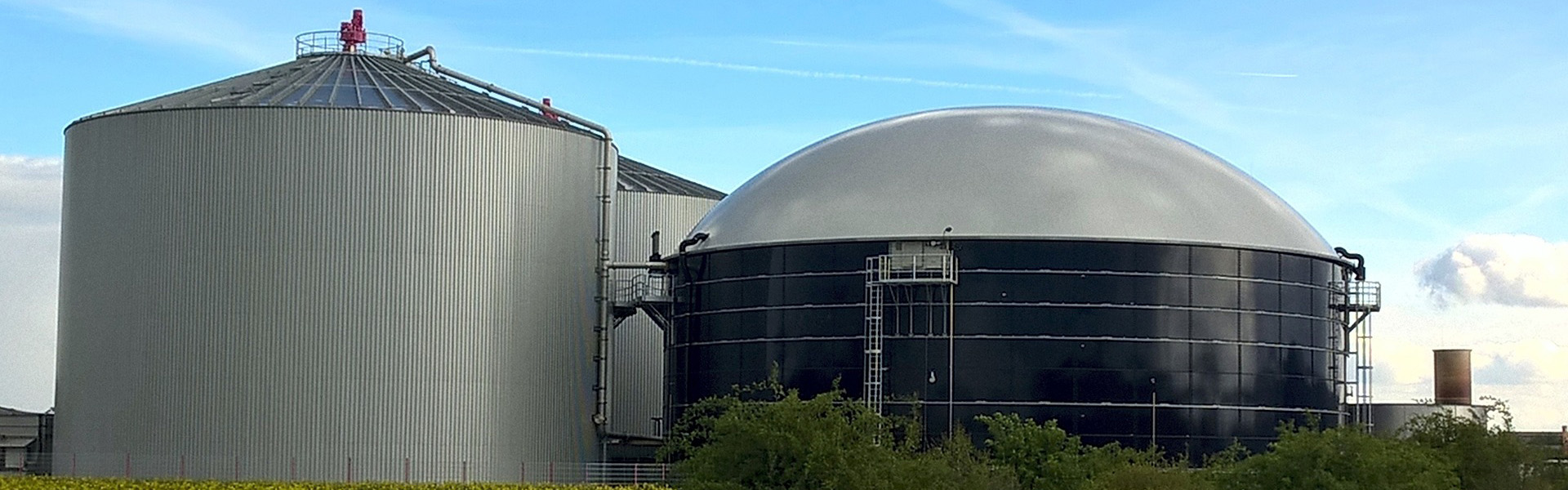
3-Stage Membrane Biogas Upgrading Architecture for High-Purity Grid Injection
Biogas produced via anaerobic digestion consists primarily of methane (50% to 65%) and carbon dioxide (35% to 50%), alongside saturating water vapor and trace chemical compounds. Transforming this raw gaseous substrate into pipeline-compliant biomethane requires the efficient stripping of carbon dioxide without allowing significant methane slippage. Modern industrial infrastructure relies increasingly on polymeric permeation units. Within a high-performance membrane biogas upgrading plant, transport phenomena driven by partial pressure differentials enable the split between fast-permeating acidic gases and slow-permeating hydrocarbons.
The operational capability of this separation methodology stems from the micro-structural configuration of glassy polymers. Compared to water-scrubbing columns or chemical absorption using amine wash solutions, dry separation setups operate without chemical reagents, avoid liquid effluent management, and demonstrate rapid startup and shutdown cycles. Achieving methane recovery levels above 99% while maintaining retentate purity above 97% mandates precise control over gas conditioning, pressure cascades, module arrangement, and thermal regimes.
Fundamentals of Polymeric Gas Permeation in Upgrading Facilities
Gas separation through polymeric barriers follows the solution-diffusion mechanism. A gaseous molecule dissolves into the high-pressure upstream face of the membrane, diffuses through the solid polymer matrix driven by its chemical potential gradient, and desorbs at the low-pressure permeate side. The permeability coefficient measures the overall flux, defined as the product of the solubility coefficient and the diffusion coefficient.
Molecules exhibit distinct kinetic diameters and condensability characteristics:
Carbon dioxide displays a kinetic diameter of 3.30 Angstroms, facilitating rapid molecular hopping through the free volume channels of glassy polymer chains.
Methane has a larger kinetic diameter of 3.80 Angstroms, significantly lowering its diffusion rate through the matrix.
Water vapor and hydrogen sulfide feature smaller kinetic dimensions and high dipole interactions, permeating through the polymer structure faster than carbon dioxide.
Oxygen (3.46 Angstroms) permeates at moderate rates, while nitrogen (3.64 Angstroms) exhibits slow permeation characteristics comparable to methane.
The ideal selectivity factor, represented by the ratio of carbon dioxide permeability to methane permeability, governs the theoretical efficiency of the polymer. Industrial installations favor asymmetric hollow-fiber configurations over flat-sheet envelopes. Hollow fibers deliver packing densities exceeding 10,000 square meters per cubic meter of pressure vessel volume. The individual fiber comprises a thin, dense selective layer (often less than 0.1 microns in thickness) supported by an integrally cast, highly porous substrate that minimizes flow resistance while providing the mechanical rigidity required to withstand transmembrane pressures exceeding 16 bar.
Gas Conditioning Protocols Upstream of Membrane Modules
Polymeric membranes maintain extreme sensitivity to condensable species, hydrocarbons, and particulates. Introducing unconditioned biogas into hollow fiber cartridges causes structural compaction, pore blockage, and irreversible plasticization. A robust membrane biogas installation therefore incorporates comprehensive pretreatment trains before pressurization and separation.
Deep Dehydration via Refrigeration and Adsorption
Raw biogas leaves digesters saturated with water vapor at temperatures between 35°C and 45°C. Water acts as a plasticizer on polyimide and polysulfone matrices, lowering mechanical strength while drastically diminishing carbon dioxide selectivity. Dehydration operates as a multi-step sequence. The primary cooling cycle reduces the bulk gas temperature to 3°C through shell-and-tube heat exchangers paired with mechanical chillers, precipitating out bulk moisture. Following primary chilling, dry desiccant or thermal swing adsorption (TSA) beds loaded with molecular sieves drop the pressure dew point to below -40°C. Maintaining the feed stream well above its saturation boundary prevents liquid condensation within the hollow fiber capillaries under elevated system pressures.
Trace Contaminant Adsorption
Biogas contains trace constituents that degrade separation media and downstream pipeline equipment:
Hydrogen sulfide causes rapid acidification and physical degradation of upstream machinery; regenerative biological desulfurization or regenerative iron oxide beds strip bulk concentrations down to under 50 ppm, followed by lead-lag activated carbon polishers removing the remainder to sub-ppm levels.
Volatile methyl siloxanes, prevalent in sewage treatment works and landfill sites, combust into abrasive silicon dioxide deposits; impregnated carbon matrices or polymeric adsorbents target total siloxane concentrations below 0.1 milligrams per normal cubic meter.
Volatile organic compounds, including halogenated hydrocarbons, terpenes, and aromatic species (benzene, toluene, xylene), dissolve readily into polymer selective layers; deep micro-pore active carbon beds intercept these compounds to prevent competitive sorption and swelling.
Aerosol Coalescence and Particulate Interception
Compressor stages introduce the possibility of trace lubricating oil carryover, even in dry-screw or oil-flooded configurations equipped with internal separators. Downstream of mechanical compression, sub-micron coalescing filtration stages capture liquid aerosols, yielding an oil content lower than 0.01 milligrams per normal cubic meter. High-efficiency particulate filters rated at 0.1 microns protect module inlet faces from migrating desiccant fines or carbon dust, preventing mechanical abrasion of the hollow fiber bundles.
Process Thermodynamics and Compression Architectures
Driving the solution-diffusion process requires establishing a continuous transmembrane chemical potential gradient, realized by elevated feed pressures. Compression stations employ multi-stage rotary screw compressors or reciprocating configurations to elevate biogas pressures between 12 and 18 barg. The compression sequence demands tight thermal control, as high gas temperatures accelerate thermal degradation of polymer structures, whereas low temperatures bring gaseous components close to their condensation limits.
Inter-stage gas coolers lower discharge temperatures, reducing the volumetric flow rate for subsequent compression stages. Prior to entering the initial membrane biogas stage, the conditioned stream passes through an electric trim heater or heat recovery exchanger to stabilize its entry temperature precisely within a 35°C to 50°C window. Modulating this temperature allows operators to tune performance: higher temperatures increase gas permeability and volumetric throughput at the expense of selective purity, while lower temperatures enhance separation selectivity while reducing overall permeation flux.
Multi-Stage Cascades and Permeate Recycle Engineering
Single-stage membrane configurations cannot simultaneously achieve high biomethane purity (greater than 97%) and elevated methane yields (greater than 99%). In a single-stage scheme, a substantial fraction of methane co-permeates with the carbon dioxide, leading to methane slip rates of 5% to 15%. Industrial upgrading installations therefore assemble modules into multi-stage cascades with internal recycle streams.
Two-Stage with Permeate Recycle
In a standard two-stage layout, conditioned feed gas enters Stage 1. The retentate from Stage 1 flows directly to Stage 2 to undergo final polishing, yielding pipeline-grade biomethane. The permeate from Stage 1, carrying the highest concentration of carbon dioxide alongside a minor fraction of methane, vents to an off-gas line or thermal oxidation unit. The permeate from Stage 2, containing substantial quantities of methane (often 20% to 40%), routes back to the suction side of the primary feed compressor. This recycling step recovers nearly all co-permeated methane, elevating overall plant recovery toward 98%.
Three-Stage Separation Configurations
Maximizing methane conservation under tight pipeline entry requirements requires advanced three-stage cascades. Stage 1 generates an intermediate retentate and a primary permeate. The retentate proceeds to Stage 2, which produces the final biomethane retentate stream. The permeate from Stage 2 recycles directly back to the inlet of Stage 1. Meanwhile, the permeate from Stage 1 feeds into Stage 3.
Stage 3 acts as an off-gas stripping barrier:
The permeate from Stage 3 exhausts as ultra-pure carbon dioxide, frequently containing less than 0.5% methane, making it suitable for direct atmospheric venting or downstream carbon dioxide liquefaction.
The retentate from Stage 3 combines with incoming raw feed gas before the compression system.
This closed-loop recycling configuration operates without external thermal inputs, achieving methane recovery rates above 99.5% within modern membrane biogas projects.
Feedstock Adaptations: Agricultural, Wastewater, and Landfill Streams
Biogas composition shifts noticeably across varied digestion substrates, requiring distinct engineering accommodations within separation trains.
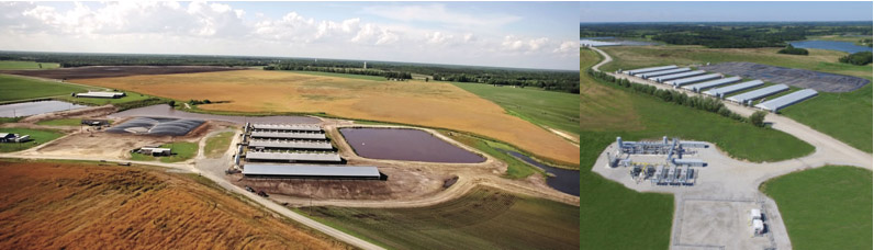
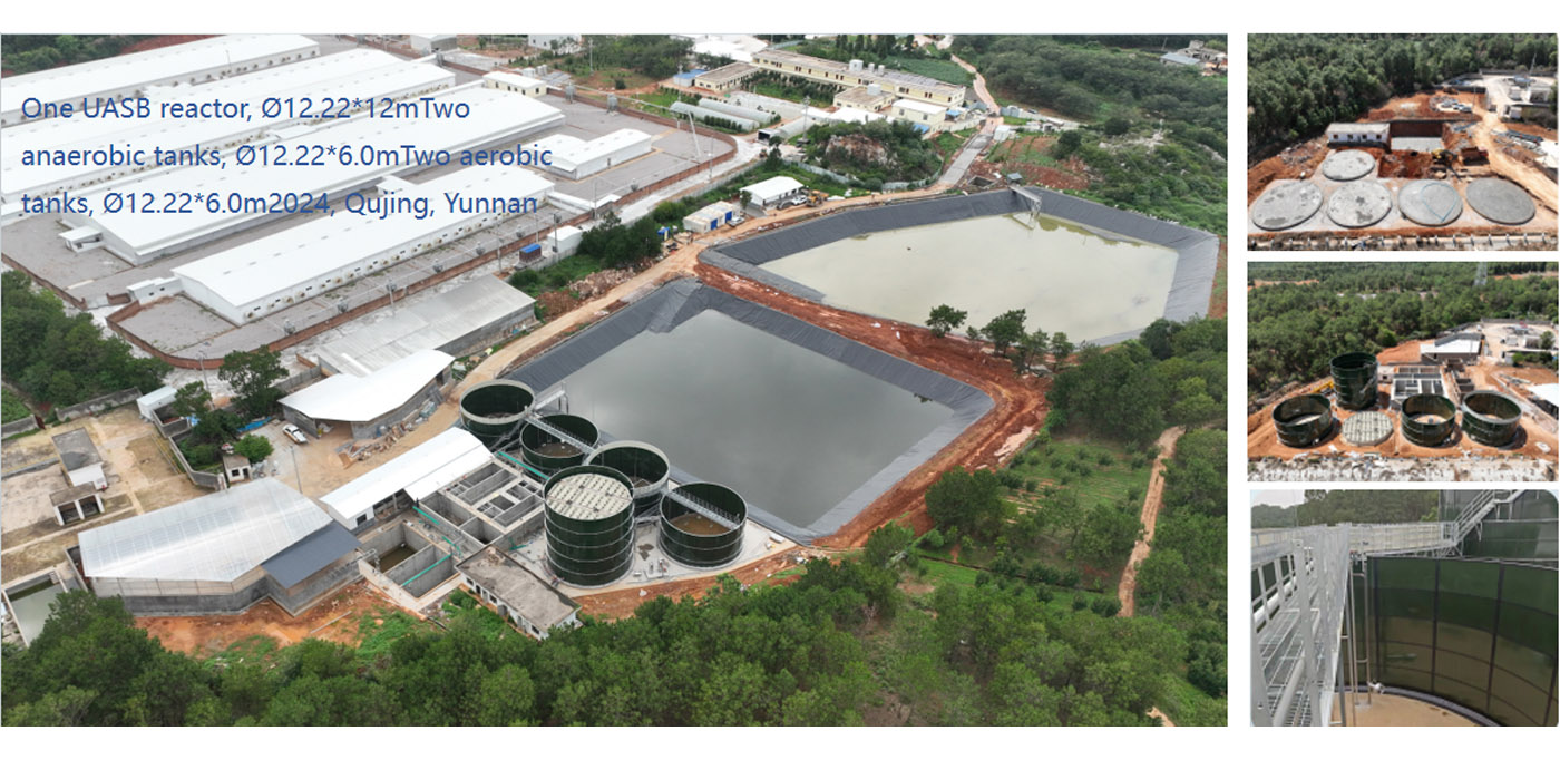
Agricultural anaerobic digesters utilizing cattle manure, corn silage, and food processing residuals deliver relatively stable gas profiles characterized by moderate carbon dioxide (38% to 42%) and high hydrogen sulfide levels (up to 3,000 ppm). Upgrading setups at agricultural operations prioritize high-capacity sulfur management trains combined with modular skid architectures. The robust modularity permits future expansion by adding parallel hollow-fiber vessels as digester volumes expand.
Municipal wastewater treatment facilities operate anaerobic digesters on waste-activated and primary sludge. This biogas features variable moisture profiles, periodic ammonia releases, and siloxane contamination originating from cosmetic and cleaning formulations. Separation systems on municipal streams require dedicated thermal swing adsorption matrices upstream of compression to strip siloxanes down to non-detectable thresholds, preventing permanent module degradation.
Landfill gas extraction sites present elevated nitrogen and oxygen concentrations caused by air ingress through waste containment barriers. Oxygen and nitrogen display permeation coefficients similar to methane across standard polyimide barriers, causing them to accumulate in the biomethane retentate stream. When pipeline injection regulations restrict total inert gas concentrations (typically nitrogen plus oxygen below 1.5% to 3%), the membrane biogas system requires integration with downstream pressure swing adsorption (PSA) polishing units or nitrogen rejection columns.
Plant Engineering Protocols and Technical Verification
Deploying a successful biomethane extraction facility demands rigorous analytical verification before fabrication commences. Gas chromatography audits should map the complete distribution of macro-components, moisture saturation bounds, and micro-contaminants across seasonal fluctuations. Engineering models compute the optimum membrane surface area, compressor stages, cooling duties, and recycle compression power based on real site variables.
Standardized factory acceptance testing protocols ensure module seal integrity, hollow-fiber potting stability, and pressure retention before field assembly. Skid-mounted designs decrease on-site civil works, condensing pre-treatment, compression, membrane racks, and safety interlocks into containerized frameworks. Automated PLC supervisory control platforms continuously adjust feed pressures, trim heater outputs, and recycle control valves, keeping biomethane specifications compliant during sudden swings in upstream digester yield.
Engineering departments, plant managers, and utility developers planning biomethane installations are invited to submit their raw biogas compositions, target grid specifications, and flow profiles. Our applications engineering group analyzes site parameters, formulates mass balance calculations, and prepares comprehensive separation equipment proposals to match specific site requirements through an engineering inquiry.
Engage our specialized engineering team today to review your project specifications, establish performance projections, and evaluate our advanced membrane biogas solutions for your facility.
Frequently Asked Questions
Q1: What is the typical methane recovery rate achieved in modern multi-stage membrane systems?
A1: Standard three-stage membrane architectures achieve methane recovery efficiencies between 99.0% and 99.7%. By recycling intermediate permeate streams back through the primary compression stage, co-permeated methane is redirected through the polymer fibers, limiting overall methane loss in the final exhaust stream to under 1%.
Q2: How do hollow-fiber membranes separate carbon dioxide from methane without chemical reagents?
A2: Separation relies on the solution-diffusion process driven by transmembrane partial pressure differences. Carbon dioxide molecules exhibit smaller kinetic diameters (3.30 Å) compared to methane molecules (3.80 Å). Consequently, carbon dioxide dissolves and diffuses through the dense polymeric layer far more rapidly, passing to the low-pressure permeate side while methane remains concentrated in the high-pressure retentate stream.
Q3: How are volatile organic compounds and siloxanes removed to protect polymer membranes?
A3: Feed preparation systems employ a succession of cooling, condensation, and deep adsorption stages. Following initial refrigeration and bulk moisture dropout, the gas flows through temperature swing adsorption (TSA) or multi-layered beds of impregnated activated carbon. These targeted media beds strip siloxanes, long-chain hydrocarbons, and halogenated compounds down to sub-ppm thresholds prior to compression.
Q4: Can a membrane separation plant handle oxygen and nitrogen present in the raw biogas?
A4: Oxygen and nitrogen permeate at rates comparable to methane through standard glassy polyimide membranes, which means they tend to stay in the retentate biomethane stream. If raw gas contains high levels of air ingress, additional downstream technologies—such as nitrogen-selective adsorption beds—must be integrated to satisfy strict gas utility grid injection parameters.
Q5: What operating pressure is required for hollow-fiber gas separation skids?
A5: Hollow-fiber modules typically operate at feed pressures ranging from 12 to 18 barg. This pressure differential provides the driving force for carbon dioxide migration across the selective membrane layer, while producing the purified biomethane retentate at near-feed pressure, which reduces recompression demands for local grid injection.
Q6: What is the expected operational lifespan of polymer membrane modules in biogas upgrading?
A6: When protected by comprehensive gas conditioning—including high-efficiency particulate filtration, oil-aerosol coalescence, desulfurization, and continuous moisture removal below saturation thresholds—hollow-fiber membrane bundles routinely demonstrate operational lifespans between 5 and 8 years of continuous duty.